Seismic Source Models#
This chapter describes the seismic source typologies supported by the OpenQuake engine: Point and Area sources for modeling distributed seismicity, Simple Fault, Complex Fault, and Characteristic Fault for modeling fault-based seismcity.
Basic concepts#
The OpenQuake engine provides several seismic source typologies to accomodate different modeling approaches. For modeling distributed seismicity, that is seismic activity occurring over a geographical region and not tied to specific well characterized fault structures, the OpenQuake engine provides the Point and Area sources. The former defines seismic activity nucleating in a single geographical location, while the second seismicity occurring uniformly over a geographical region. Both sources define a seismogenic layer which constrains rupture location and extension along depth. A collection of Point sources can be used to model seismicity with spatially variable parameters (as obtained from a smoothed seismicity approach for instance), while Area sources can be used to model seismicity in geographic zones usually defined by expert judgments taking into account seismological, geological and geodetic information. Both source typologies allow for the modeling of earthquake ruptures as extended surfaces (that is as rectangular planes) with potentially multiple orientations and inclinations (that is multiple strike and dip angles) and also placed at different depth levels. Earthquake ruptures can extend without barriers along strike but cannot cross the seismogenic layer.
For modeling fault-based seismicity, that is seismic activity occurring on a well identified and characterized fault zone, the OpenQuake engine provides three main options, the Simple Fault, the Complex Fault and the Characteristic Fault sources.
The Simple and Complex Faults distribute seismicity uniformly over a fault surface, with the only constraint that an earthquake rupture cannot extend outside of the defined fault surface. In both sources an earthquake of a given magnitude is defined as a portion of the fault surface. To simulate all possible rupture locations, an earthquake rupture is moved, or floated, over the entire fault surface. The two source typologies differ instead in terms of the geometrical complexity they can accommodate when modeling a fault surface. In particular, a Simple Fault source can model a fault surface as a plain rectangle in the simplest case, or as a set of connected parallelograms in the most complex case. A Complex Fault source can instead model an arbitrarily complex quadrilateral surface, which can therefore accommodate changes in dip angle along depth or along strike or changes in fault width. The Complex Fault source is therefore particularly suitable for modeling large subdution interface faults, while Simple Fault sources can be used for modeling crustal faults.
The Characteristic Fault source can model both simple and complex geometries, but instead of simulating floating ruptures, each earthquake breaks the entire fault surface independently of the associated magnitude. The Characteristic Source typology can be used to model individual faults or fault segments that tend to produce essentially same size earthquakes (Schwartz and Coppersmith, 1984).
Independently of the typology, all sources require the definition of the following main parameters:
magnitude-frequency distribution
temporal occurrence model
tectonic region type
magnitude-area scaling relationship (for all but the Characteristic Fault source)
rupture-aspect ratio (for all but the Characteristic Fault source)
upper seismogenic depth
lower seismogenic depth
The magnitude-frequency distribution defines the total moment rate released by a source as well as the relative frequency of earthquakes of different magnitude that can be generated by this source. It is therefore a key object controlling the influence of a source in a PSHA.
The OpenQuake engine supports the definition of the traditional double-truncated Gutenberg-Richter magnitude-frequency distribution which is widely used in PSHA. The parameters required for its definition are the \(a-value\) (defined as the intercept of the cumulative distribution at \(M = 0\) in a \(\log_{10}\) scale), the \(b-value\), the minimum and the maximum magnitudes. In order to accommodate other possible parametric (and non-parametric) forms of the magnitude-frequency distribution, the OpenQuake engine provides a generic discrete Incremental magnitude-frequency distribution defined through a list of annual occurrence rates, associated to an equally spaced set of magnitude values. The OQ-hazardlib contains also a implementation of the Youngs and Coppersmith (1985) magnitude-frequency distribution. This distribution is currently non available in the OpenQuake engine. With future releases, we plan to make this distribution available to the OpenQuake engine users.
In a PSHA, the magnitude-frequency distribution is subject to a discretization process which defines a set of equally spaced magnitude bins and the associated annual occurrence rates (for an Incremental magnitude-frequency distribution such a discretization is part of its definition). For each source, the annual occurrence rate associated to a magnitude bin is uniformly distributed over all the ruptures associated to the same magnitude bin value. In other words, while the particular geometry of a source determines location and number of ruptures of a given magnitude, the occurrence rate (and thus the occurrence probability) is uniform over ruptures with the same magnitude.
The temporal occurrence model defines the functional form used to compute the probability of the number of rupture occurrences in a given time span based on the occurrence rate specified by the magnitude frequency distribution, that is the term \(P_{rup_{ij}}(k|T)\) in the equation above. Currently the OpenQuake engine defines only the Poissonian model but other functional forms can be introduced.
The tectonic region type is an attribute used as a key to associate a seismic source to a ground motion model. Given a source model describing seismicity occurring in a region including different tectonic settings, the associated ground motion model may prescribe different equations for the different tectonic settings. The mapping between a ground motion model equation and a seismic source is therefore achieved through the tectonic region type attribute.
All sources typologies supported by the OpenQuake engine generate ruptures as extended surfaces.
Table summarizing parameters, and their functions, required for the definition of Area and Point sources in the OpenQuake engine
Parameter |
Purpose |
|---|---|
Magnitude frequency distribution |
Defines total moment rate and the relative frequency of earthquakes of different magnitude |
Temporal occurrence model |
Defines functional form for the calculation of the probability of the number of rupture occurences in a given time span |
Magnitude area scaling relationship Rupture aspect ratio (length / width) |
Define sizes and shapes of rupture planes |
Nodal plane distribution (each nodal plane being defined by strike, dip, rake) |
Defines orientations and faulting styles of ruptures |
Hypocentral depth distribution |
Defines centroids of rupture planes |
Upper seismogenic depth Lower seismogenic depth |
Constrains rupture planes inside seismogenic layer |
With the only exception of the Characteristic Fault source, the area of an earthquake rupture surface is magnitude dependent. To constrain the rupture surface area, the Point, Area, Simple and Complex Fault sources require the definition of a magnitude-area scaling relationship. This parameter together with a rupture aspect ratio (defined as ratio between length and width) completely define the rupture extension and shape (assumed rectangular). Indeed, indicating with \(A\) the rupture area and with \(ar\) the rupture aspect ratio, rupture length (\(L\)) and and width (\(W\)) can be computed as:
In all sources, the rupture aspect ratio is used to constrain the initial rupture shape. However, if this conflicts with other source-dependent geometrical constrains, the rupture is reshaped so as to conserve the area as given by the scaling relationship.
The upper and lower seismogenic depths define the seismogenic layer, that is the depth range over which earthquake ruptures can extend. The definition of a seismogenic layer is required to avoid an uncontrolled extension of the earthquake ruptures along depth which can lead, especially for large magnitude events, to unrealistic scenarios. The definition of a seismogenic layer thickness effectively induces a magnitude-dependent rupture aspect ratio. Indeed, as the rupture size increases with increasing magnitude values, the rupture width reaches the maximum allowed width, and the rupture aspect ratio starts deviating, that is increasing, from the original value.
The Point and Area sources#
The parameters specific to the definition of Point and Area sources, and their associated function, are listed in Table 3.1. Sources are parameterized so that earthquake ruptures are modeled as rectangular planes. In a point-source representation (Figure 3.1) ruptures are generated underneath a single geographical location, and can be potentially distributed over multiple orientations, faulting styles, and depth levels. Rupture centroids are co-located with the point- source location and are positioned at depths specified by the hypocentral depth distribution. Rupture shapes follow the given aspect ratio. However, if for a given aspect ratio and hypocentral depth the rupture plane crosses either boundary (upper or lower) of the seismogenic layer, the plane is shifted along the dip direction so as to fit within the upper and lower seismogenic depths. As a consequence, the hypocentral location no longer corresponds with the plane centroid. If this adjustment is insufficient to avoid crossing either boundary of the seismogenic layer, the plane is reshaped; the width becomes the maximum allowed by the seismogenic layer thickness, and the length is increased so as to conserve rupture area (at the expense of the aspect ratio).
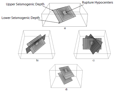
Graphical representation of the earthquake ruptures as generated by a Point Source. a) Given a geographical location on the Earth surface, ruptures are generated underneath according to a scaling relationship and aspect ratio value and forced to not exceed the upper and lower seismogenic depths. Ruptures can be distributed over multiple dips b), strikes c) and hypocentral depths d).#
In an area source, earthquake ruptures are distributed over a regular grid (equally- spaced in distance) covering a geographical region as defined by a seismic zone. Generation of ruptures follows the same algorithm as for point sources.
For both sources, the rate associated to each rupture plane is the original rate associated to the corresponding magnitude bin, scaled by the location weight (1 for a point source and 1/N for an area source, where N is the total number of grid points in the area), the nodal plane (that is orientation and faulting style) weight, and the hypocentral depth weight.
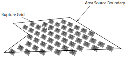
Earthquake ruptures generated by an area source in the OpenQuake engine. Ruptures are distributed uniformly over a regular grid within the area. In this plot, for better visualization, ruptures are modeled only according to a single nodal plane and hypocentral depth, but actual calculations may involve multiple orientations and hypocentral depths. Ruptures originating from different grid nodes may also overlap and cross each other.#
For an area source, the boundary is assumed ‘leaky’, that is earthquake ruptures can extend out of it. Because of rupture area conservation, earthquake surfaces associated to large magnitudes can extend well beyond the source boundaries. If the rupture orientation is considered random then this behavior can potentially lead to unrealistic scenarios, that is earthquake ruptures that are not consistent with the area geometry and the tectonic feature it is meant to represent. The design of an area source requires therefore a careful estimation not only of the associated activity rates but also of the predominant faulting orientations.
The OpenQuake engine does not currently provide the possibility to define non-leaky boundaries. The main difficulty in the implementation of such a feature is the definition of a clear algorithm specifying how hard boundaries would influence the generation of earthquake ruptures within the area source. Several options are available. The easiest approach would be to remove, from the set of generated ruptures, the ones that extend outside of the boundary. This approach requires however a careful calculation of the occurrence rates to be assigned to the earthquake ruptures. These cannot be calculated anymore a priori (that is from the number of grid points in the area source), but only after all the ruptures have been generated and the ones crossing the boundary excluded. Additionally, the removal of ruptures may also introduce a non-uniform hazard pattern within the area source. An alternative approach would be to truncate earthquake rupture surfaces that extend outside of the area boundary. However, without a careful analysis of the consistency between the main rupture orientations and source geometry, this approach may potentially lead to large magnitude events developing over very small rupture surfaces. A third approach would be to adjust the earthquake orientation/location so that the rupture surface does not extend beyond the area boundary. Depending on the source geometry, such an adjustment may not be always possible (that is, there may no be an orientation/location which allows a rupture to fully lie within the area source). This last strategy can be seen as a way to minimize the rupture extension outside of the area source.
The Simple Fault source#
Parameters required for the definition of a Simple Fault source are given in the table below. The fault surface is constructed by translating the fault trace (defined as the intersection between the fault surface and the Earth s surface) from the upper to the lower seismogenic depth along a direction perpendicular to the fault trace strike (measured as the azimuth of the great circle line connection the first and last coordinates of the trace) and with an inclination equal to the dip angle. The surface so defined is effectively modeled as a regular (i.e. equally spaced in distance) mesh. For each magnitude bin defined in the magnitude-frequency distribution, an earthquake rupture is modeled as a portion of the fault surface, accordingly with the magnitude scaling relationship and the rupture aspect ratio. To simulate all possible rupture locations, each earthquake rupture is floated, that is moved, along both the strike and dip directions. The floating step is assumed equal to the mesh discretization step. The occurrence rate associated to a given magnitude bin is distributed uniformly over all the ruptures associated with the same magnitude value.
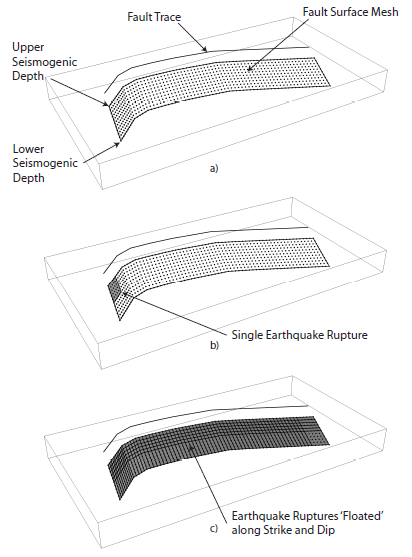
Simple Fault source in the OpenQuake engine. The fault surface is obtained by translating the fault trace from the Earth’s surface to the lower seismogenic depth with an inclination equal to the dip angle. The upper seismogenic depth delimits the fault top edge. A mesh representation of the fault surface is then constructed a). An earthquake rupture is defined as a portion of the fault surface b), and all possible rupture locations are simulated by floating the rupture surface both along strike and along dip c)#
Table summarizing parameters, and their functions, required for the definition of a Simple Fault source in the OpenQuake engine
Parameter |
Purpose |
|---|---|
Magnitude frequency distribution |
Defines total moment rate and the relative frequency of earthquakes of different magnitude |
Temporal occurrence model |
Defines functional form for the calculation of the probability of the number of rupture occurrences in a given time span |
Magnitude area scaling relationship Rupture aspect ratio (length / width) |
Define sizes and shapes of rupture planes |
Fault trace Upper seismogenic depth Lower seismogenic depth Dip angle |
Define fault surface |
Rake angle |
Defines faulting style |
The rupture floating algorithm for a Simple Fault source#
We describe here in more detail the algorithm adopted for modeling floating ruptures in a Simple Fault source. We indicate with \(\Delta\) the mesh spacing, and with \(n^{fault}_{strike}\) and \(n^{fault}_{dip}\) the number of nodes along the strike and dip directions in the mesh representing the entire fault surface. By indicating with \(L(M)\) and \(W(M)\) the length and width of a rupture of magnitude M, the equivalent number of nodes (along strike and dip) representing a rupture on the mesh can be computed as:
By further assuming that a rupture is floated along strike and dip with a step equal to the mesh spacing (D), we can compute the total number of ruptures along strike and dip as:
Since a rupture can propagate until its boundary reaches the fault boundary, but not beyond, the total number of possible rupture locations along a certain dimension is equal to the total number of nodes minus the number of nodes required by the rupture reduced by 1, which represents the number of positions that a rupture cannot occupy because it would otherwise extend, at least by one mesh spacing, outside of the fault boundary. Indicating with \(\nu(M)\) the annual occurrence rate as given by the magnitude-frequency distribution, the annual occurrence rate associated to each rupture of magnitude M is given by:
The occurrence rate scaling factor is therefore magnitude dependent (in contrast with the Area Source where the scaling is constant for all magnitudes).
Table summarizing parameters, and their functions, required for the definition of a Complex Fault source in the OpenQuake engine
Parameter |
Purpose |
|---|---|
Magnitude frequency distribution |
Defines total moment rate and the relative frequency of earthquakes of different magnitude |
Temporal occurrence model |
Defines functional form for the calculation of the probability of the number of rupture occurrences in a given time span |
Magnitude area scaling relationship Rupture aspect ratio (length / width) |
Define sizes and shapes of rupture planes |
Top edge Intermediate edges (optional) Bottom edge |
Define fault surface |
Rake angle |
Defines faulting style |
The Complex Fault source#
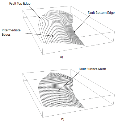
Parameters required for the definition of a Complex Fault source are given in the table above. To accommodate the definition of irregular geometries, the Complex Fault source requires the specification of the coordinates of, at least, the top and bottom edges of the fault surface, and optionally, of one or more intermediate edges. Edges can have different and variable directions and a single edge can develop over different depth levels. This gives a very large flexibility in the definition of the fault surface, allowing for changes in width and inclination both along strike and along dip.
Mesh construction in a Complex Fault source#
The fault edges are used to construct a mesh representing the fault surface. The mesh is, in general, not uniform; that is, the mesh spacing may be spatially variable to accommodate the irregular geometry of the surface. The construction of the mesh relies on the following algorithm. By indicating with \(\bar{L_{edge}}\) the average edge length, and with D the desired mesh spacing, the number of mesh points along the strike direction is computed as:
Each edge is then resampled into \(n_{strike}\) points. By connecting the different edges along nodes that are on the same positions, dipping lines can be constructed. By indicating with \(\bar{W}_{fault}\) the average fault width computed from the set of dipping lines, the number of mesh points along dip is computed as:
Complex Fault source#
Each dipping line is then resampled into \(n_{dip}\) points. This completes the construction of the mesh which is therefore represented by \(n_{strike} \times n_{dip}\) nodes. It is worth noticing how the resampling of the edges as well as of the dipping lines allows the construction of a rectangular mesh which is however non-uniform. The actual mesh spacing varies from values smaller than \(\Delta\), in regions where the fault length or width is smaller than the corresponding average, to values larger than \(\Delta\) where the opposite occurs. \(\Delta\), which is basically used to compute the number of nodes along strike and dip, should therefore be considered as an average mesh spacing.
The rupture floating algorithm for a Complex Fault source#
The non-uniformity of the mesh representing the fault surface makes the rupture floating algorithm for a Complex Fault source more problematic than for a Simple Fault source. Indeed, because of the variation of the actual mesh spacing, it is not possible to rely on the mesh spacing \(\Delta\) to compute the number of nodes required by a rupture of a given magnitude. For each possible rupture location, an optimization procedure is used instead which identifies the number of nodes along strike and dip which gives a mesh surface with an area that is the closest to the one predicted by the magnitude area scaling relationship. In other words, the rupture mesh is represented by a number of nodes which is not constant but that may vary along the fault surface. In this context, the rupture aspect ratio is used to define the length of the rupture top edge, while the rupture width results from the optimization procedure. Such optimization procedure is well exemplified in the figure below. The fault surface represents a southward dipping subduction fault located north of Panama defined in the model for South America developed by (Petersen et al., 2010). The figures shows how a \(M=7.7\) event is modeled in two different parts of the fault surface. Where the fault is narrow (the western part) the rupture mesh contains a large number of nodes, separated by a small distance. Where the fault is large (the eastern part), the rupture mesh contains fewer nodes but separated by a larger distance.
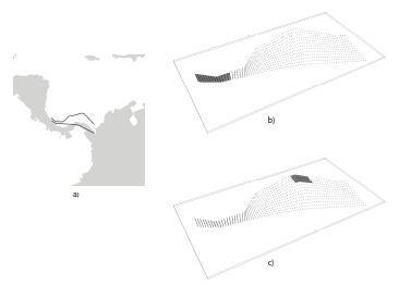
a) Example of Complex Fault source representing subduction interface fault in North of Panama (Petersen et al., 2010). The mesh modeling a :math:`M = 7.7` *event is depicted in the eastern part#
The Characteristic Fault source#
The Characteristic Fault source is meant to represent individual faults or fault segments that tend to produce earthquakes (Schwartz and Coppersmith, 1984) of essentially the same size. To offer the greatest flexibility in the definition of the associated geometry, a Characteristic Fault can be defined in terms of a simple fault geometry or as a complex fault geometry. A third option is available, that is a collection of planar ruptures, which can be used to model multi-segment ruptures for instance. In a Characteristic fault, earthquake ruptures always break the entire fault surface, therefore the rupture floating mechanism is not needed.
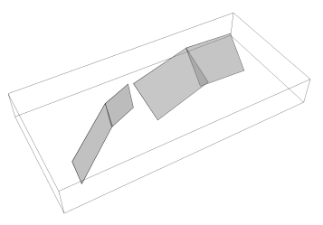
Example of Characteristic Fault sources defined through a collection of planar surfaces modeling a multi-segment rupture#